Areas are used for calculating flow quantities in sewer network system. In this command, user can define three different types of areas that are used for calculating different flow quantities. There are catchment areas that are used for calculating rain flow; influence areas for house waste flow and influence areas for industrial flows.
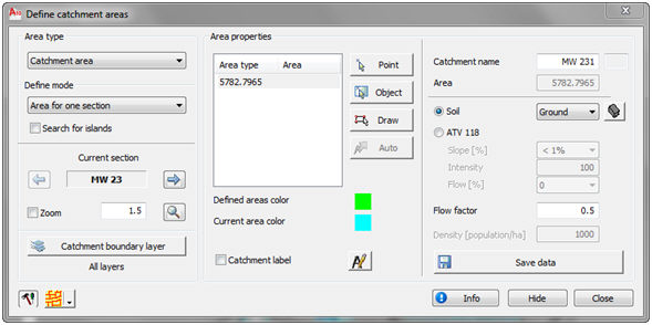
Starting command "Define area" opens the dialogue shown on the previous picture. First step after opening this dialogue is to select work area. After that user must, from the drop down list in upper left corner, select the type of area that will be defined (catchment area, house or industrial influence area).
Catchment area represent the area from which, all rain that fells on that area, comes in the section to which that catchment area belong. One part of that water is lost because of the infiltration into the ground, which depends on the character of the terrain. The amount of water that comes into the section, in relation to the amount of rain that fell on that area, is regulated with "Flow factor". That factor is entered in right part of the dialogue.
Influence area for house waste flow represents the area from which the house wastewaters are gathered for certain part of the sewer system. For this option, user must also enter population density (population/ha). Later in the process of calculating waste flows, user must enter house waste water flow coefficient (as l/s on 1000 inhabitants) and using that data calculate the flow.
With influence area for industrial waste, only the area is entered in this step, while later, for the calculation, user must also enter wastewater flow coefficient (l/s × ha), and those two elements are used for calculating flow.
The data about the area is saved for every section individually. One section can have one or more catchment areas. One catchment area can be divided into several sections. It is not necessary that all sections have defined areas.
There are four ways for defining areas: "Area for one section", "Area for multiple sections", "Automatic defining" and "Direct input data to section". Define mode is selected from the drop down list in the left part of the dialogue.
There are three ways for entering areas: by picking point inside closed area, by selecting closed polyline or by drawing closed area. Any of these ways of entering area can be used for defining area for one section or area for multiple sections.
When the option "Area for one section" is selected, user must first select the section whose area will be defined. Section is selected using buttons “Previous” and “Next section”, and then the area is defined.
If one section has several catchment areas defined, rain flow is calculated using total catchment area and average coefficient of flow.
Total area ![]()
Average flow coefficient ![]()
The total influence area and average density of inhabitants are calculated on the same way as shown above, and they are used for calculating the house wastewater flow on section with several influence areas.
Option "Area for multiple sections" is used for defining one area for all sections selected as work area. When one area is defined for several sections (for example, for the whole array), the area is distributed according to length of sections. First, the total length of all sections is calculated, and then the percentage of on section in total length is calculated. That percentage is than multiplied with the total area, which results with area for that section. That is shown with formula:
![]()
where is:
Ai ………..part of total catchment area that belongs to section „i“
Asum……..total catchment area
li………….length of section „i“
![]() ……..total length of all sections
……..total length of all sections
When the option "Automatic defining" is selected, the program automatically recognizes the area for the sections selected in the work area. Automatic defining can define, in very short period, a very large number of areas, under condition that area boundaries are set according to certain rules. Automatic defining can define only one area for certain section. The process of defining is based on following: one point on the section is selected (middle of section), and than the program searches for the closed polygon around that point using the Boundary algorithm. If that algorithm is found, it represents area for that section. If one bigger area, that includes several sections, is defined, the same polygon will be defined for all those sections. Program has control that takes only one polygon into consideration (other ignores) and divides it by all sections by criteria of length (the biggest area belongs to the longest section). In this way, it is necessary to draw only outside boundary of areas along some longer channel, and program will distribute areas on sections quite well. After selecting this option and entering all other needed data, user must start button “Automatic recognition” to define the areas.
Using option "Direct input data to section", the areas are not defined in the drawing, but the value of the area is entered directly into a dialogue ("Area" field in the right part of the dialogue). This option is useful when there are already measured values of area for certain sections, so that values just need to be entered in the dialogue.
It is often the case that inside one area, there is a part that has different settings (for example, for catchment area that part can have different flow factor). That part must be subtracted from that area. If that part is set up as an island (surrounded with same area from all sides), when the option "Search for islands" is active, the program will automatically find islands and subtract them from the area.
When the option "Catchment area" is active, program will draw label for every defined area. Activating button “Define catchment label” opens the dialogue for defining catchment labels that is shown on the next picture.
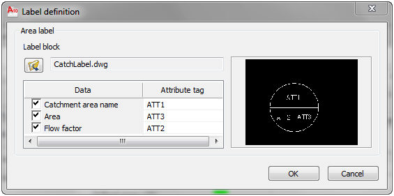
Right part of the dialogue shows the default label block (CatchLabel.dwg). User can select some other block he defined using button ”Open file”. Left part of the dialogue is used for selecting the data that will be written in the catchment label (index, area and flow factor), and selecting in which block attribute will that data be entered. After selecting certain data, drop down list appears in the "Attribute tag" field. That list show tags of all attributes in the selected block. Activating button "OK" closes the dialogue and the user is returned to the "Define area" dialogue.
Button "Catchment boundary layer" opens the dialogue where user can select one or more layers that contain boundaries of areas. When defining areas, the program will search for boundaries only on selected layers. That option is very useful in cases when the option for searching islands is active and the drawing includes elements that could be recognized as islands, and they are not islands. The dialogue for selecting boundary layers is shown on the next picture.
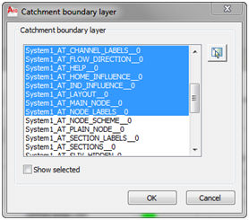
The list shows the names of all layers defined in the drawing. User must select the layers that contain area boundaries. Layers can be selected in the list (click, Ctrl+click, Shift+click), or they can be selected in the drawing after activating “Select in the drawing” button. If the option "Show selected" is active, the list will show only the selected layers. Button "OK" is used for closing this dialogue and returning to the "Define area" dialogue.
Flow factor is a very important data for catchment area for rain flow. That factor represent relation between the amount of water that comes in the system and the total amount of water that fell on some area. Flow factor can have a value between 0 and 1. Program has two predefined soil types (Ground and Asphalt) and their flow factors. For creating new soil types user must start the button "Soil type catalogue" which will open the following dialogue.
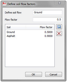
Central part of the dialogue shows the list of all defined soil types and their flow factors. To define a new soil type, user must enter a name and flow factor for that soil type in the fields at the top of the dialogue. After activating button “Save”, that new soil type is saved and it is shown in the list in the dialogue. To erase the definition of certain soil type, select that type in the list and activate button “Erase”.
After closing "Define soil flow factors" dialogue, the "Define area" dialogue is active again. In that dialogue user has to select soil type for the certain area. Soil type is selected from the "Soil" drop down list. After that, the "Flow factor" field shows the flow factor defined for that soil type. That flow factor can be changed by entering new value in that field.
Areas can be defined in several ways – by selecting a point inside closed area, by selecting a closed polyline or by drawing a closed area.
Areas must be closed shapes. They can be made using closed elements (Polyline) or they can be made from several elements (LINE, …). Urbano 7 uses three basic algorithms for selecting areas: selecting existing closed elements, creating closed elements using AutoCAD Boundary function, or drawing closed element. Defining areas is similar to the AutoCAD Hatch command. When using this Boundary option by selecting the point inside some polygon, user must have in mind the limitations of this AutoCAD function (primary the reliability of the algorithm for real surveying coordinates).
After activating button “Pick point inside closed area” user must pick inside some closed area in the drawing. The area must be completely bordered with elements (line, polyline) that are on layers selected in "Catchment boundary layers" dialogue. After activating button “Select closed polyline” user must select in the drawing closed polyline, while after activating button “Draw closed area” user must draw the borders of the area in the drawing.
After selecting in the drawing, the selected area is hatched and marked yellow in the drawing, and the list shows its type and area. If the option for searching islands was active, the data about found islands will also be shown in the dialogue. After activating button "Save data", the data about that area will be saved in the selected section (or sections), and the label for that area will be drawn in the drawing. When defining area for section that already has defined areas, existing areas will be hatched and marked green, so they could be noticed easier.
The colours for marking observed (yellow) and previously defined (green) area are shown in upper right part of the dialogue, and they can be changed in general settings dialogue. Underneath that, the index number and the area for the certain area are shown. Fields Ground, Flow factor and Slope are active when entering catchment areas, while the field Density [population/ha] is active when entering influence area for house waste flow.