To create new section label, select Labels, Sections – New. Add the data using data picker and label the elements using previously described methods.
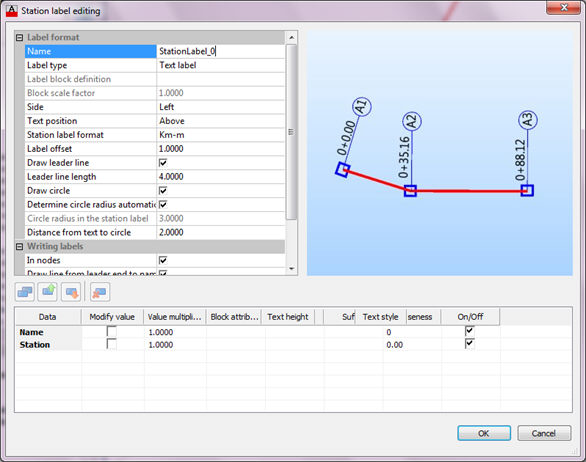
To create new station label, select Labels, Sections – New station label.
Station labels can be used to mark selected nodes inside of the drawing with their station information according to the position in the network system. You can adjust station format, leader length, text height, circle diameter and many others.

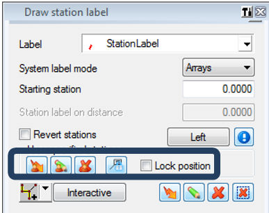
To label elements with station label, double click on the label you created (or on the predefined one), and the following modeless dialog will appear:
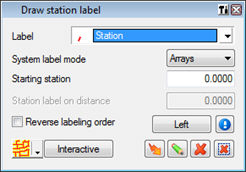
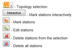
Select label mode and starting station. After that, select topology to label stations (array, branch, from node to node..).
 The most important thing about station lables is that, when you label
certain topology selection with stations and than change positions of
some nodes within the selection, the
stations get updated.
If you set stations to be marked in nodes, new nodes will be marked with stations as well, and stations will be changed regarding topology change – node move.
You can move nodes in longitudinal sections as well – their stations will be updated.
It is possible to define station label at any point on the section. Also, station label works dynamically in two ways: the first one preserves label position on the section and changes station value, and the second one preserves station value and changes station label position.
On the pictures below, there are examples of ‘classical’ station labels (only in the nodes) and arbitrary station labels:
Classical station labelling in the nodes |
Station labels in arbitrary points |
|
|
The emphasized row of the options above is made for arbitrary station labelling:
- ![]() Before
station labelling, it is necessary to define the range for labelling,
using option from the node to the node (or array, branch). After that,
labelling in arbitrary points can be performed
Before
station labelling, it is necessary to define the range for labelling,
using option from the node to the node (or array, branch). After that,
labelling in arbitrary points can be performed
- ![]() It
is possible to draw stations in arbitrary points, on the sequence where
the group of station labels already exists. Program automatically knows
where the starting point of the label group is and the value of the starting
label (since it doesn’t have to start from zero). After selecting the
station group, it is necessary to pick the position of arbitrary station
labels
It
is possible to draw stations in arbitrary points, on the sequence where
the group of station labels already exists. Program automatically knows
where the starting point of the label group is and the value of the starting
label (since it doesn’t have to start from zero). After selecting the
station group, it is necessary to pick the position of arbitrary station
labels
- ![]() Erasing
of arbitrary station labels
Erasing
of arbitrary station labels
- ![]() Changing
of station label status from locked position to unlocked position and
vice versa
Changing
of station label status from locked position to unlocked position and
vice versa
- ![]() Possibility
to define behaviour of the station label after editing the network. As
mentioned above, the arbitrary station label can work dynamically:
Possibility
to define behaviour of the station label after editing the network. As
mentioned above, the arbitrary station label can work dynamically:
Initial labelling before editing |
Locked position after editing |
Unlocked position after editing |
|
|
|
It is possible to label pipeline with the stations according to polyline, which basically represents road alignment.
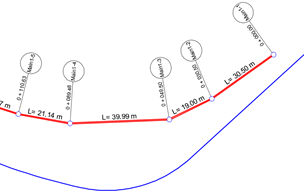
Station labels exist in the nodes and show cumulative length of the sections, from the beginning up to the certain node.
If we would like to label stations according to specific polyline, every node is projected perpendicular on that polyline. Then cumulative length calculation is performed by summarizing polyline lengths, as shown on below picture:
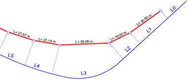
So, station labelling according to polyline (alignment) should respect length on the polyline, between points which are perpendicular projections of pipeline nodes to the polyline. In that way station according to polyline can look like below:
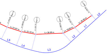
The command for station labelling according to polyline can be started from the panel (Labels -> RC -> Label station based on polyline), as shown on below picture:
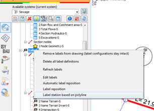
When the command is started the next dialog appears:
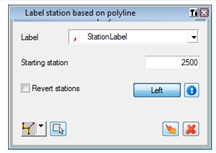
Common stations and stations according to polylines use the same label configuration. In the dialog, it is necessary to select some array and related polyline. It is possible to define starting station of the first node in the pipeline.
In longitudinal section the new component is added, which can be found together with usual stations in the longitudinal section:
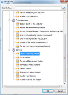
In the longitudinal section it is possible to have two bands together, pipeline stations and stations based on polylines, as shown on below picture:
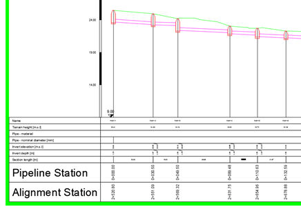
Band of stations based on polyline in longitudinal section will be written when real projection and labelling in layout is done.
It is worthy to mention that, like all other station labels, stations according to polyline are dynamic. It means that any move of the pipeline nodes will automatically update station values. Automatic update reacts only when nodes of the pipeline are moved. If polyline is changed, stations will stay unchanged (it is necessary to label pipeline again to refresh the labels).
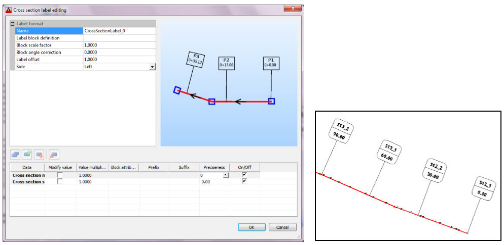
Cross section labels are represented as perpendicular lines on selected station on the system. Cross section labels are useful to mark the cross section position on the layout network.
To create new section label, select Labels, Sections – New cross section label.
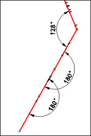
Angle labels can be used to show horizontal angle values between sections of the layout network. Angle labels are connected to the dimension style definition of AutoCAD.
To create new section label, select Labels, Sections – New angle label.
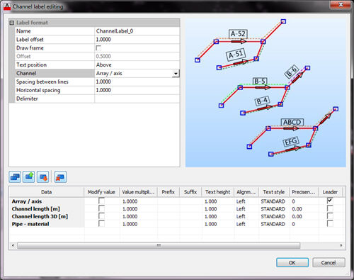
Channel labels is used to label arrays or branches instead of each section. To create new section label, select Labels, Sections – New channel label.
This label
can
be created the same way as other label configuration. You
can
add arbitrary number of various data to the channel label, using data
picker  :
:
