This command is used for assigning equipment to nodes. Equipment types are predefined, and user cannot create new types. Node equipment can be tanks, pumps, different types of valves, air release, and mud release.
NODE - the position of horizontal or vertical break on the route and places where water goes out or come in the network
RESERVOIR - nodes that represent an infinite external source or sink of water to the network. They are used to model such things as lakes, rivers, groundwater aquifers, and tie-ins to other systems.
TANK - nodes with storage capacity, where the volume of stored water can vary with time during a simulation.
EMITTER -
PUMP - device that impart energy to a fluid thereby raising its hydraulic head.
VALVES - used to control the pressure or flow at a specific point in the network.
MUD RELEASE - it is positioned in the lowest points of the route and it is used for releasing of the accumulated mud
AIR RELEASE - it is positioned in the highest points of the route and it is used for releasing of air from the pipes.
Connection point - system geometry point
Mud release and air release are not important for the hydraulic calculations but their position is shown in longitudinal sections.
The following table shows all node equipment types and data that have to be entered for the hydraulic calculation and the data that is not necessary but can be entered.
With "Node equipment" command only the position of the equipment is given. Basic data is taken from node data and other data is entered using command "Additional hydraulic data".
Every water supply network must have mud-release and air-release placed on specific places (in lowest and highest breaks in level line). Besides that, to be able to run the calculation for some system, that system must have tank or reservoir in it.
The dialogue of this command is shown on the following picture:
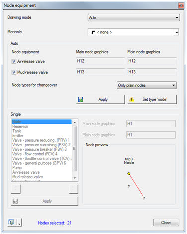
Equipment can be entered in two ways: auto or single. That is selected from the "Drawing mode" drop down list at the top of the dialogue.
Option "Auto" is used only for entering air-release and mud-release valves. Other equipment types must be entered with option "Single". With option "Auto" the program automatically search for nodes that are higher than all their neighbouring nodes an in them place the air-releases, and in nodes that are lower than their neighbouring nodes place the mud-releases.
After selecting this drawing mode, user must select which equipment will be entered (by turning on or turning off the check marks next to the air-release and mud-release valve options). For each option, it is possible to select graphics for that type of equipment in main and in plain nodes by selecting it from adequate drop down list.
Also, it is possible to select the node types for changeover. If the option "All types of nodes" is selected, air-release and mud-release valves will be placed in selected positions no matter which node type was in that position before that (for instance, air-release valve will be placed in the position of the tank). When the option "Only plain nodes" is selected, air-release and mud-release valve will be placed only in ordinary nodes (nodes that under equipment have "Node").
After activating button "Apply" the program will enter air-release and/or mud releases in appropriate positions. Button "Reset" is used for deleting the air-releases and mud-releases entered with the last use of option "Auto".
When the drawing mode "Single" is selected, user enters equipment individually for every node. From the list on the left side of the dialogue the equipment type (node, reservoir, tank, emitter, different valves, pump, air-release and mud-release valve) that will be used for certain node must be selected. Drop down lists for main and plain node graphics automatically shows the graphics for the selected equipment type, but user can also select some other graphic from that lists.
Right part of the dialogue shows the schematic preview of the selected node. The preview shows the name of the current node, equipment that is currently in it, and terrain elevations in that and in all neighbouring nodes.
With "Single" drawing mode user
has to enter the air-releases and mud-releases on its own, but the program
suggest the positions where they should be placed. So, the ![]() sign represent the position where air-release should
be placed, and
sign represent the position where air-release should
be placed, and ![]() represent the
position where the mud-release should be placed.
represent the
position where the mud-release should be placed.
After activating button "Apply" the equipment selected in the list is placed in the current node.
Buttons “Previous/Next Node” are used for moving to the previous or next node.
Equipment can also be entered using command "Layout -> Edit system elements -> Node -> tab Equipment", but this command is adapted to the specifics of the entering equipment in water supply systems.