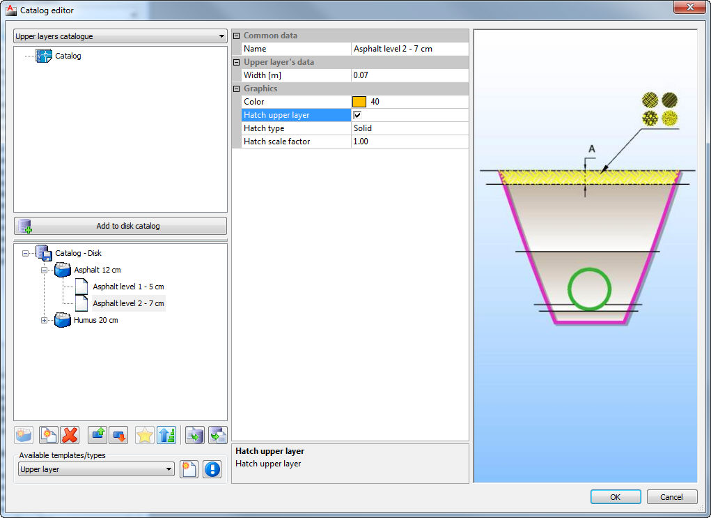

Catalogs represent the storage of the predefined items (pipes, manholes, trenches..). Default catalogs will be created when you install Urbano. You can use those defualut items in pipe design in every drawing when working with Urbano. It is possible to create new items, erase existing ones, edit and copy items. It is possible to export/import catalogs from/to XML files.
In every catalog it is possible to create catalog group, and in each group it is possible to create catalog items according to availabe item templates.
In some catalogs it is possible to create catalog subgroups within catalog group.
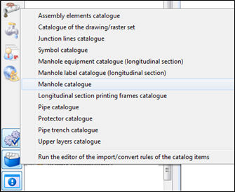
The following catalogs are available:
- Catalog of assembly elements
- Catalog of curves/patterns (Hydra)
- Catalog junction lines
- Catalog of geodetic symbols
- Catalog of additional network data
- Catalog of manhole equipment (longitudinal section)
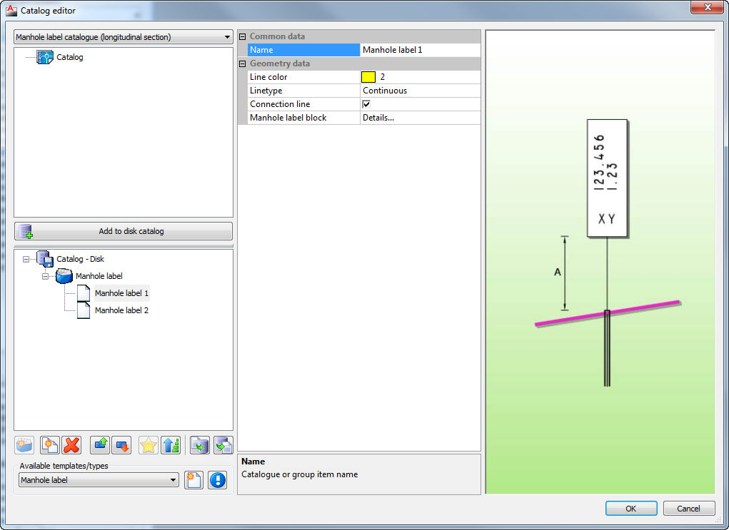
- Catalog for manhole labels (longitudinal section)
- Catalog of manholes
- Catalog of prefabricated manhole elements
- Catalog of printing frames (longitudinal section)
- Catalog of pipes
- Catalog of protecting pipes
- Catalog of trenches
- Catalog of upper layers
- Run the rule editor of the import/convert rules of catalog items
 Click
on the Catalog icon and choose which
catalog would you like to open:
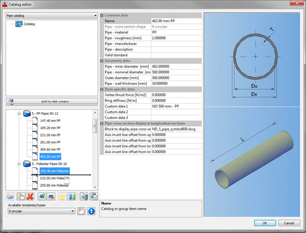
Following dialog will be opened:
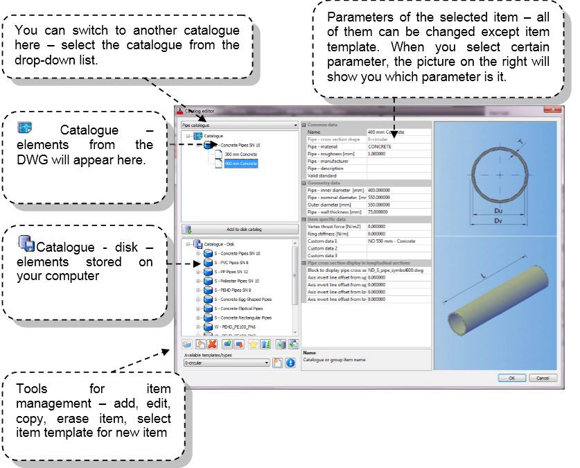
 - This icon represents DWG
file. Upper part of the dialog will show the items stored in that particular
DWG. You can't use those items in your future work. To be able to do that,
select those items or the whole group, and add it to your Disk catalog
by pressing the button
 -
This icon represents disk. Lower part of the dialog will show all items
stored on your disk. If you add items from the drawing to your catalog
on the disk, you will be able to use it in your future work.
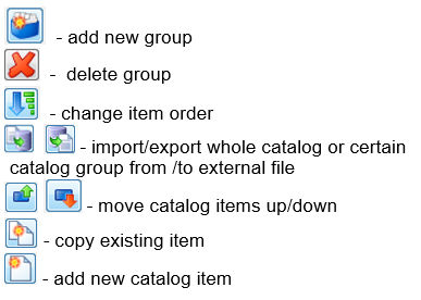
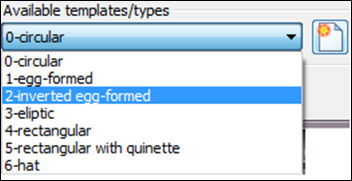
- add new item according to available template
Important:
The easiest way to create new group of items that are similar to existing one (i.e. items are similar, but with
some different parameters) is to create new group, copy existing items and drag& drop them to the new group,
than change some parameters.
It is possible to edit catalog group of items using group edit (for example, one group of pipes). In the sheet view,
it is possible to see all pipes (or manholes or …) in table view and check all the data. It is much easier to control
data by simple comparison and edit it directly in the table. In addition, it is much easier to find and correct any kind of error.
Another significant option is that it is possible to copy and paste elements or certain data of elements, to and from Excel.
Group edit is available for three catalog types – pipe catalog, manhole catalog and prefabricated parts for the concrete manholes.
Sheet view can be started by the command Edit group data (select group – right click):
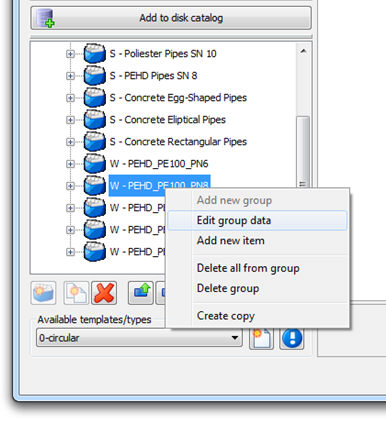
When the command is started, sheet view appears:
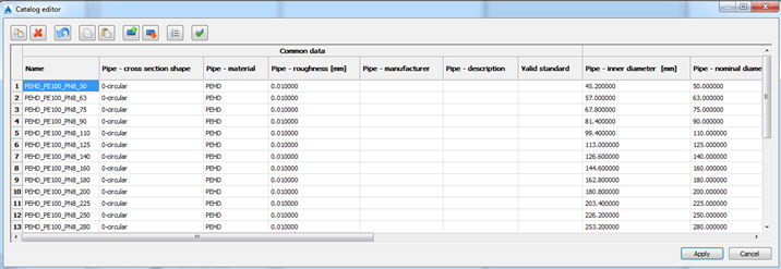
All the data from the catalog is available in the sheet view.
Working with sheet view is not dynamic – the program will not save and changes in the catalog until you click Apply.
Cells will change color after editing:
- when edited, cells will change the color (to yellow).
- when some new items were added (new pipes), those items will become green.
- when some items were erased, it will be marked with red color.
- If you just close the sheet view (Cancel button), all the changes will be abandoned.
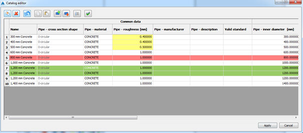
In sheet view, following actions are available:
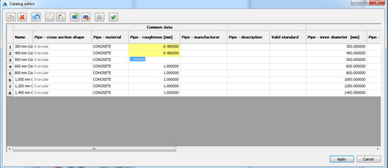
Single cell editing - To edit the cell, double click on it and type the value. Editing is finished with Enter (or click to another cell).
When you press Enter, the program will automatically move cursor to the next cell, and you can continue to change values,
as shown on the picture below:
 - Add
new item. It
is very easy to add new items in the catalog group. The program will add
new item as the copy of the existing one. If you want to create new element
based on some particular element, place the cursor on that element, and
click this button.
It works this way, because the sheet view allows you to create similar items only. If you are working with group of circular pipes, you can add only circular pipe. It is also not possible to use sheet view to work with group that contains items of different types.
 - Erase existing items.
 -
Undo. This
button will undo changes.
 - Copy one or more
cells
 - Paste one or more
cells
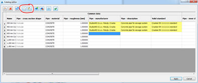
 - Copy
and paste functionality - It
is quite often that the user wants to copy only certain cells. For example,
you can add some text in the cell column Pipe manufacturer, and then paste
it to all other cells. You can paste the data one by one. It is also possible
to copy and paste more values (i.e. Pipe manufacturer, Pipe description
and Valid standard) as shown on the picture below:
 -
Move item up
 -
Move item down
 -
Restore catalog order
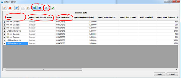
Sorting of items in the catalog
It is possible to sort items by any value - just pick header of the value. In addition, it is possible to move below
up and down, if the order is not appropriate. Also, if necessary, it is possible to restore original order.
 - Select all cells
Exchange the catalog with Excel
Catalog items can be copied to external application (usually Excel). Catalog values can be edited there using
advanced techniques of the application (i.e. multiple copy and paste). After that, content can be pasted back to
sheet view. This way, working with the catalog can be very efficient. It is possible to export some part of the catalog
and paste back only values that are changed in external application. User should be careful when pasting back the
values, to position cursor precisely where this partial content should be pasted. If paste origin is not correctly defined,
the values will not be correct. The right procedure is shown in few steps below:
a) Selecting partial content of catalog for copy
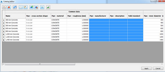
Just the values of Pipe manufacturer, Pipe description and Valid standard are copied.
b) Editing in Excel
Content pasted to Excel before editing |
Content after editing in Excel |
|
|
c) Pasting back to sheet view
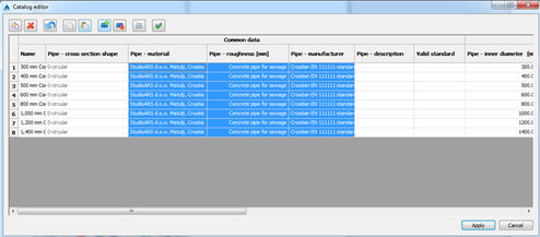
It is very important to properly select right cells before pasting. If it is not the case, mistake can
happen like shown below:
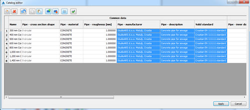
So the values are moved to wrong cells (pipe material takes manufacturer, roughness has values of
description and so on). It is important to mention that it is not possible to create new item in
external source (add new row) and paste it back to Urbano catalog sheet view. To import values
from external source, it is necessary to create appropriate number of items.
 How to create or modify catalog,
catalog groups and items.
1) Click on Catalog-Disk in the lower part of the dialog
2) Add new group. If you want to add new element in the existing group, select that group.
3) Than select item template and click the icon Add new item
4) Input item parameters
5) When you finish, press enter
6) In order to save the changes (new groups, elements) click OK.
7) If you made a mistake, simply click Cancel. The program will not save the changes.
To be able to use curves and patterns in Hydra, it is necessary to create it in the catalog:
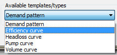
When you create curve/pattern, you have to define the data:
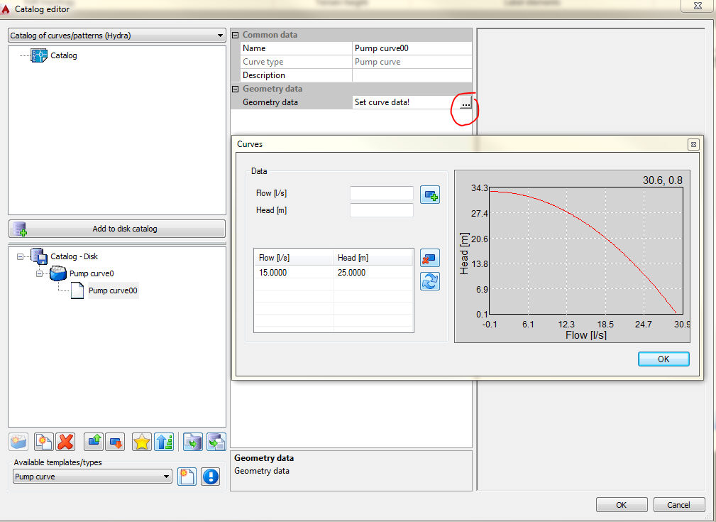
This data are used for calculations in Epanet, which is used for hydraulic calculations in Hydra. The principle of creating curves in Hydra is identical to creating curves in Epanet.
Pump curve represents the relationship between the head and flow rate that pump can deliver at its nominal speed setting.
If there is only one point defined, the program will create curve based only on that one point. That point represent pump's desired operating point. To create curve program calculates two more points by assuming that when the flow is zero, the head is equal to 133% of head in the entered point, and when head is zero the flow is two times bigger than the flow in the entered point. Program tries to fit that three points into one curve with the form H=a - bQc (where H is head, Q is flow and a, b and c are constants).
If more than one pair of points is entered, the curve is created by connecting the points with strait-line segments.
For variable speed pumps, the pump curve shifts as the speed changes. The relationships between flow (Q) and head (H) at speeds N1 and N2 are:

Volume curve determines how storage tank volume varies as a function of water level. It is used when it is necessary to accurately represent tanks whose cross sectional area varies with height. The lower and upper water levels supplied for the curve must contain the lower and upper levels between which the tank operates.
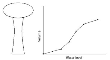
Efficiency curve determines pump efficiency (%) as a function of pump flow rate. Efficiency takes into account mechanical losses in the pump itself as well as electrical losses in the pump's motor. The curve is used only for energy calculations. If not supplied for a specific pump than a fixed global pump efficiency will be used.
Head loss curve is used to describe the head loss through a General purpose valve as a function of flow rate. It provides the capability to model devices and situations with unique head loss – flow relationships such as reduced flow- backflow prevention valves, turbines, and so on.
Time pattern is a collection of multipliers that can be applied to a quantity to allow it to vary over time. Nodal demands, reservoir heads and pump schedules can have time patterns associated with them.
The dialogue of this command is shown on the following picture:
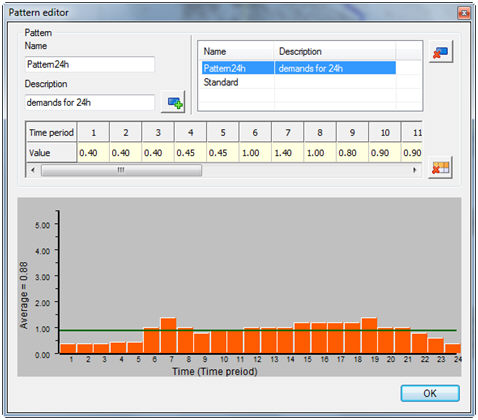
Pattern time step is equal for all patterns and it is set in command "Hydra -> Calculation". By default, that value is one hour. For example, assume that we have node with demand 10 l/s and pattern time step is set 4 hours. If we give to that node the following pattern:

Than the actual demand in that node through time will be as follows:
![]()
After the time exceeds the given number of pattern time steps, the pattern wraps around to its first period again. If five periods were lasting one hour each, after five hours the first period is repeated again.
Additional data has to be defined in the catalog. When we open additional data catalog, the options are as following:
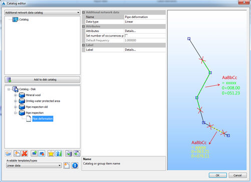
Every additional data can have arbitrary number of attributes. Attributes can be defined by picking in the field Details. The following dialog opens:
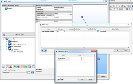
By using the icons in the lower left corner, it is possible to create or delete attribute data. Data type can be text, integer or real. It is possible to define default value. If you want the data to have some predefined values, it is possible to define it. When assigning data, the user will be able to pick the value from the pop-down list.
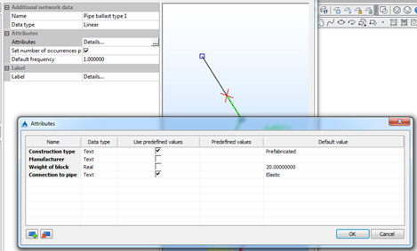
Example of attributes:

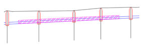
Sometimes, additional data can have repetitive occurrence. Examples are ballast or cathodic protection. The difference between “usual” and “repetitive” additional data are described on the picture below:
Continuous data Continuous data with frequency

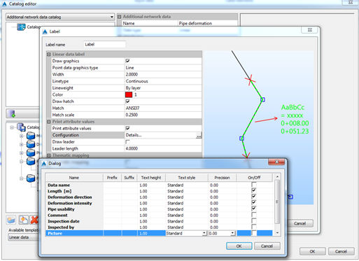
Label definition can be created in the catalog, too. When selecting Label details, the following dialog appears:
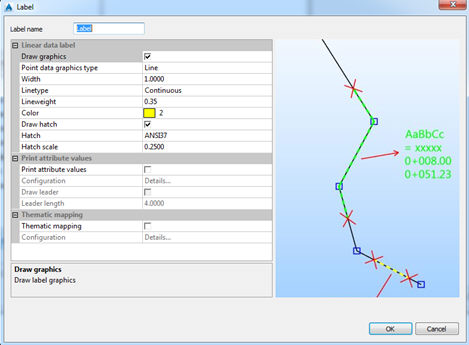
In addition to graphical labelling (buffer or circle), it is possible to show some attributes in labels. To do that, it is necessary to check on option Print attribute values. It is possible to select which data will be used in text label, as shown on the picture below (Details):
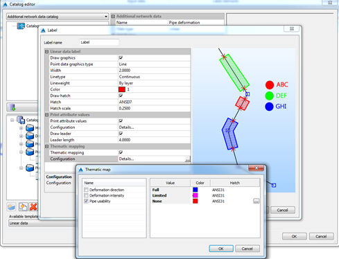
It is also possible to assign different color of additional data, related with certain attribute values. This way it is possible to emphasize some values of additional data.
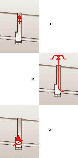
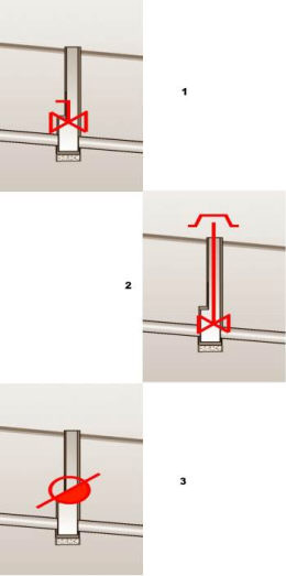
In the design of water distribution networks exists some specific equipment of the manholes like air vents, hydrants, pumps, sludge valves, siphons and general type valves. All the equipment can be drawn in longitudinal sections in manholes. But first all these equipment have to be defined in the catalog.
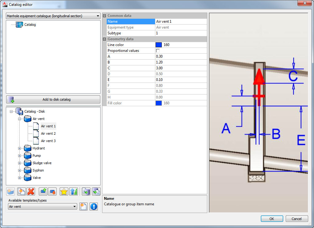
Manhole equipment types which can be defined in the catalogue:
PUMP EMITTER MUD-RELEASE VALVE
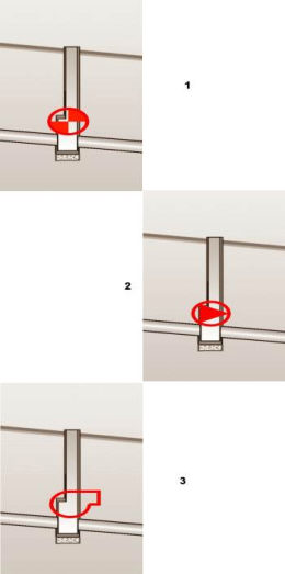
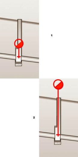
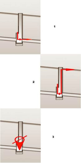
AIR-RELEASE VALVE SYPHON VALVE
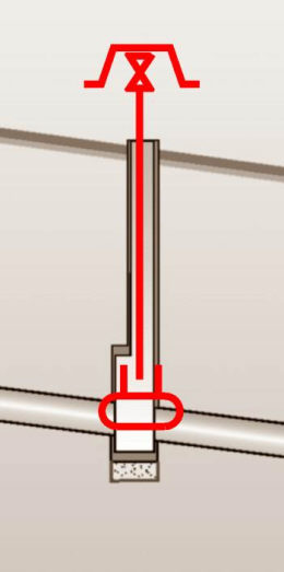
Catalog of manhole labels contains definitions of label which can be drawn in longitudinal sections to label the manholes with some particular data about manholes.
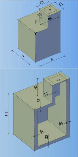
Catalog of all defined manholes which can be used in the drawing. In the catalogue can be defined 8 different types of manholes according to shape, and every shape can contain arbitrary number of elements with different dimensions.

Types of manholes which can be defined in the catalogue:
MANHOLE TYPE 0 MANHOLE TYPE 1 MANHOLE TYPE 2 MANHOLE TYPE 3
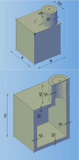
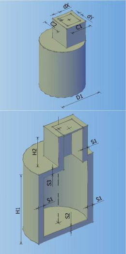
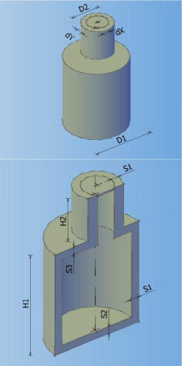
MANHOLE TYPE 4 MANHOLE TYPE 5 MANHOLE TYPE 6 MANHOLE TYPE 7
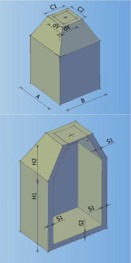
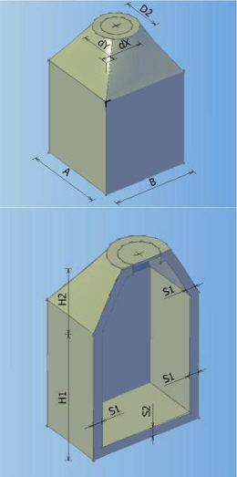
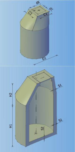
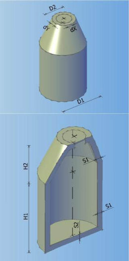
It is possible to create ten element types of prefabricated components. Components can be both circular and rectangular.
All components stated in DIN 4034-1h have already been created in the catalog – ten groups of components according to EN and DIN
standard. Since only round components were defined in the standards, only round components were created in Urbano catalog as
well, although it is possible to create rectangular components, too.
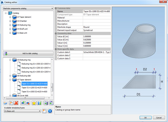
Users can use those components, or change components and groups to fit their requirements. They can use existing elements or create
new ones, same as in all other catalogs.
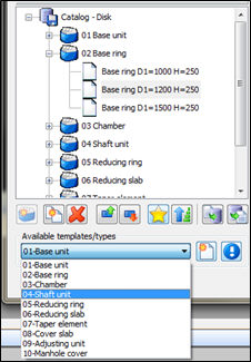
To create new components, it is necessary to create new item, based on element type, as shown on the picture:
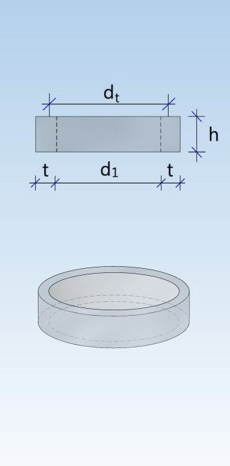
When you create element based on element template, you will be able to define element dimensions; picture on the left side of the dialog
will show you what value does the properly refers to.
Types of prefabricated elements:
Base unit (DIN 4034-1: Schachtunterteil)
Base ring (DIN 4034-1: Fußauflagering)
Chamber ( (DIN
4034-1: Schachtring)
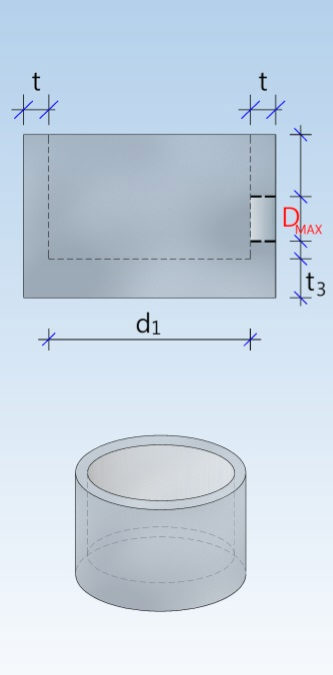
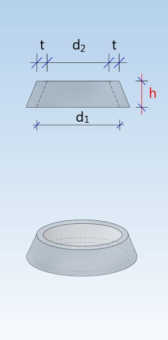
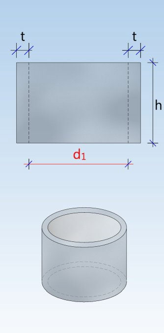
Shaft unit (DIN 4034-1: Schachtrohr) Reducing ring (DIN 4034-1: Übergangsring) Reducing slab (DIN 4034-1: Übergangsplatte)
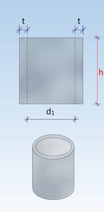
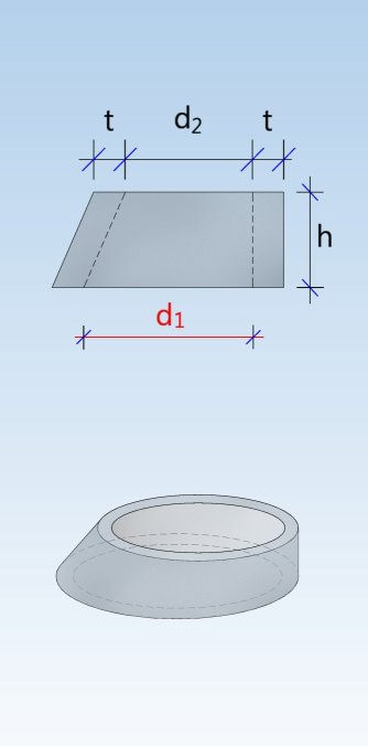
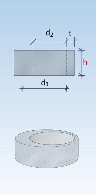
Taper element (DIN 4034-1: Schachthals) Cover slab (DIN 4034-1: Abdeckplatte) Adjusting unit (DIN 4034-1: Auflagering)
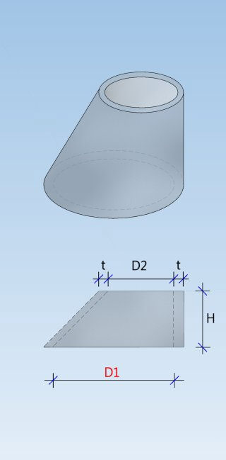
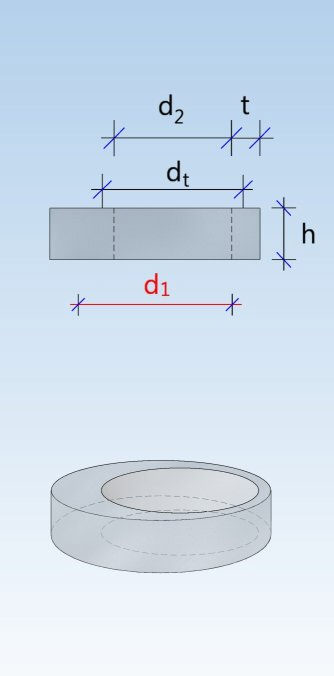
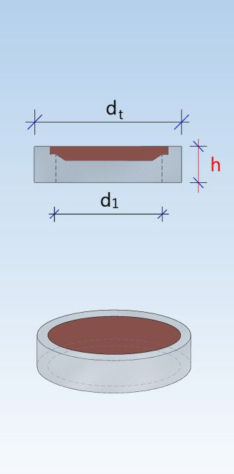
Manhole cover
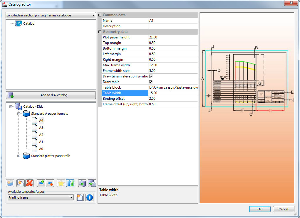
Catalog of frames which can be used for printing longitudinal section, after braking according to defined parameters.
Catalog of pipes defined by the pipe manufacturer or by the user, according to material, diameter, strength and any other parameter. All defined pipes in the catalogue can be used in the drawing and for calculations.
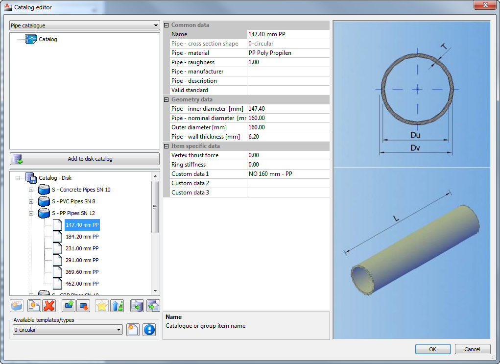
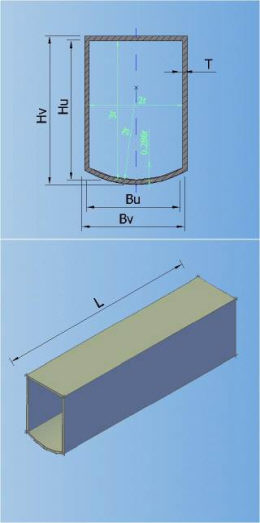
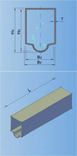
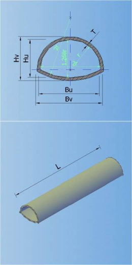
In the catalogue can be defined 7 types of default shapes of the cross section (circular, egg-formed, inverted egg-formed, elliptic, rectangular, rectangular with cunette, and hat):
0-CIRCULAR 1-EGG-FORMED 2-INVERTED-EGG-FORM 3-ELIPTIC

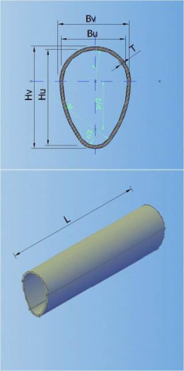
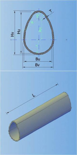
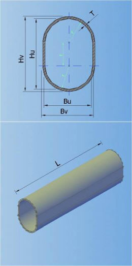
4-RECTANGULAR 5-RECTANGULAR WITH CUNETTE 6-HAT
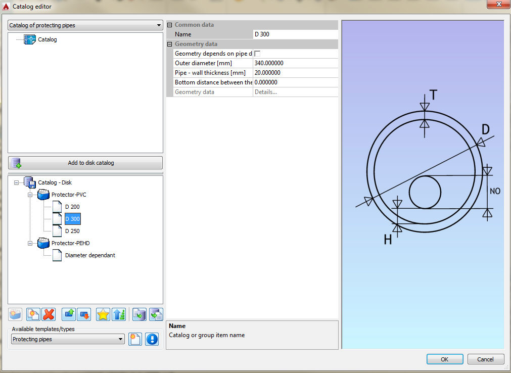
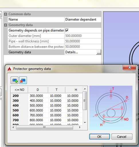
Protecting pipes can be created in two way - with defined diameter and with diameter that depends of the main pipe diameter:
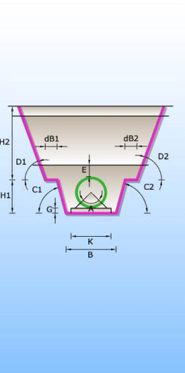
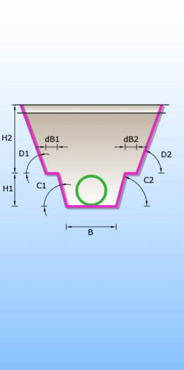
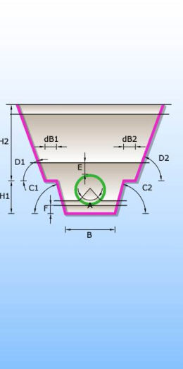
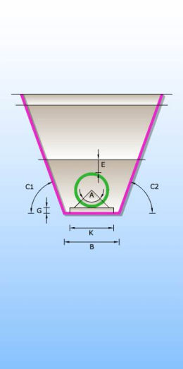
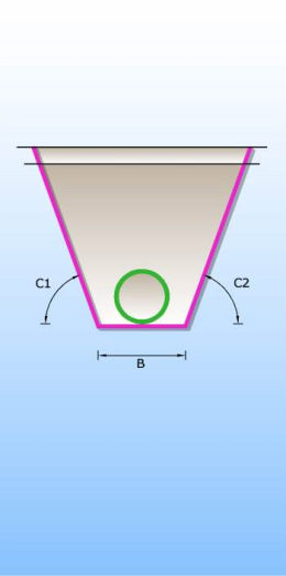
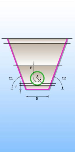
Catalogue of trenches in which pipes are laid. There are 6 different types of trenches according to type of bed and shape of trench (single and double trench; sand, concrete and no bed). Trenches definition are used for excavation calculation.
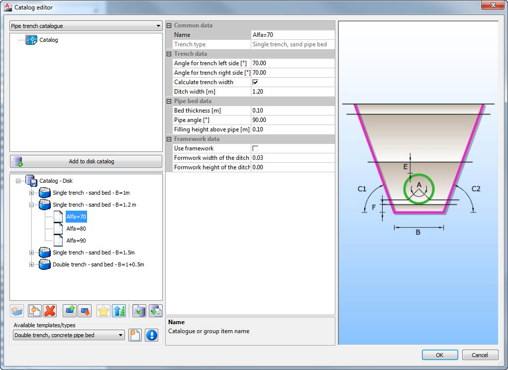
If the option Calculate trench width is selected, single trench will be drawn, and program will select the width of the trench according to European standard EN 1610 and DIN standards 18300 and 4124. Selected trench width depends on the pipe diameter, the angle of the trench sides, and it depends on the fact if there is a form work on the trench sides or not; or on trench depth.
The value for trench width is obtained from two tables. In first table the width is obtained from pipe diameter and the angles of the trench sides, and in another the width is obtained from trench depth. The bigger of these two values for certain cross section is taken as the trench width.

DOUBLE TRENCHES
CONCRETE PIPE BED SAND PIPE BED WITHOUT PIPE BED
SINGLE TRENCHES
CONCRETE PIPE BED SAND PIPE BED WITHOUT PIPE BED
Catalog with upper layers which contains definitions of upper layers, layers near the surface of terrain which are important for the cost of excavation.
One group can contain arbitrary number of layers. When the user assigns certain upper layer for the pipes, basically he assigns entire group with all layers
of the group.
