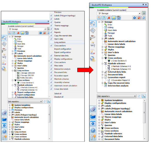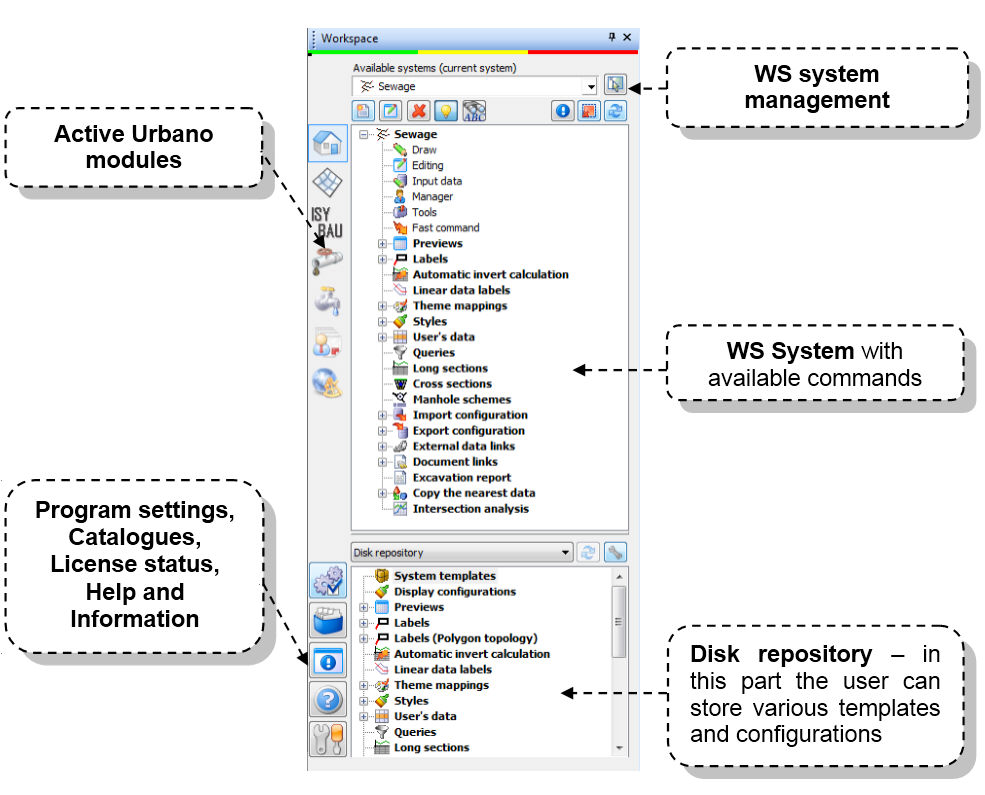
Urbano Workspace Panel - WS contains all Urbano commands, organized into groups and subgroups. You can start the commnad either using mouse – double click (DC), either mouse right-click (RC). Except commands, Urbano can contain configurations as well. You can create arbitrary number of configurations with various properties, change it whenever you like, save it and use it in another drawings.
When you start AutoCAD profile with Urbano, Workspace will appear automatically. It is modeless, which means that it will be active all the time. You can turn it off the same way as all windows – by „X“ button. When you want to start WS again, just type „WS“ in the CAD command line.

Frequently used Urbano commands take place on ribbon. Urbano ribbon is created dynamically when Urbano starts.


To change ribbon settings, type command "SAUI" in command line (Studio ARS User Interface). The program prompts you to define ribbon type.
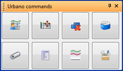
If you type "1", the ribbon will not show command names, only tooltips and icons:

If you type "0", the ribbon will show command names, tooltips and icons.

User can select toolbar commands by himself.
To customize Urbano toolbar, use Program settings - Urbano commands, and mark commands that you want to use in the toolbar. To activate toolbar, click on Show toolbar.
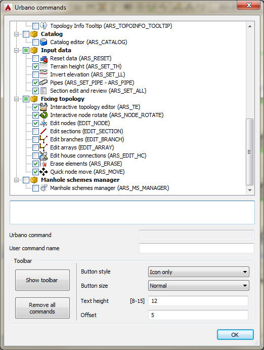
The toolbar will appear immediately. It is possible to define button style in the dialog. There are three options – Icon only, Icon with text and Text only. In addition, it is possible to choose among three options of icon size – Large, Normal and Small. There is possibility to define text size on the icon and its offset.
Toolbar can look as follows:
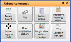
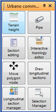
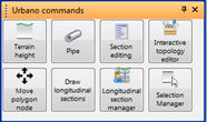
Toolbar is resizable. Icons will rearrange according to shape of toolbar. This way it is possible to have different shapes, which fit well to current user needs:
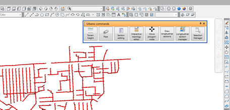
Toolbar can float on drawing area or it can snap to any edge of the program window, as shown on the pictures below:

Dynamic table can be permanently available on the screen, in a floating dialog. You can position in anywhere on the screen or even on second monitor. It has many options for selection.
The most important feature is the possibility to change/edit certain data shown in table view. Automatic data update is available too, so any action regarding Urbano elements (changed data) should be automatically available.
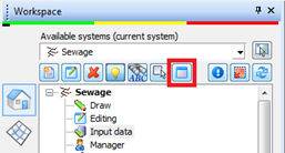
To show dynamic table click on the button on top of the Workspace, as shown on the picture below:
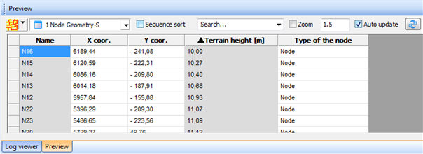
By default, table view will appear at the screen bottom:
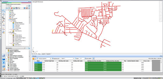
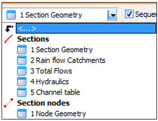
Table view use configurations from Preview, created in the Workspace. You can use any of those configurations, both for nodes and for sections. If you change the configuration, it will be automatically available in the configuration list, as shown on the picture below:

It is possible to define configuration of table view according to arrays or branches. If you want the table view to be created for arrays/branches, you have to specify it in upper right list, as shown on the picture below:
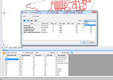

When you create the configuration for table, the program proposes scope for sections by default. If you want to create tables with scope for arrays/branches, you have to take care about the data that you want to show in the table. If you select the data that varies along the branch or array, the program will show the data for all sections, separated by “;” sign:

If you have assigned the same pipe diameter and the same slope for entire branch, the program will show one value:


How to work with the table:
 Selection.
When you open the table, the program
will show you the list of all elements of the system. To select certain
part of network, use standard selection button. The selection remains
active in the table until you change it, the program doesn’t reset it.
 -
Sorting
elements. It is possible to sort elements by any data column;
the program will sort elements according data type. If you turn on Sequence sort option, the
program will sort elements by arrays.
Configuration. It is possible to select table configuration from the drop-down list. As described earlier, all configurations must be created in the Workspace – Previews.
 - Search. It
is possible to search for elements by typing text in the search box. The
program will find all elements that contain it. When you type the text,
press Enter – the program will automatically show all elements that contain
data with this text. After few searches, it is also possible to reach
search history, by opening pull-down list of the search box.
 - Zoom.
If
you check Zoom,
program will zoom to the selected topology element (node or section) and
mark it. If you select more elements in the table, the program will zoom
to all elements at once, and mark it. It is possible to control zoom size
using zoom factor (by default - 1.5).
 -
Update. If
you check Auto update, the values shown in the table will be changed automatically
if you change them. For example, if you set section geometry table as
active and you change section name or invert elevation, the table will
be updated automatically.
 - If you turn off auto update, you can refresh table changes with refresh
button.
 - Recapitulation
message. In the upper right corner of the table, there is
dynamic recapitulation message. The program will show you total numbers
of selected elements, and total length (for sections).

Example for sections: Section: 3 (145.50 m) / 1036 (41981.98 m)
Example for nodes: Nodes: 3/1038
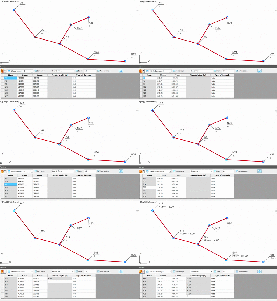
One of the most important features of table view is the possibility to edit certain data directly in the table. There is many data in Urbano that is either defined or calculated. All the data that the user can define, can be edited in the table. Data calculated by program cannot be edited in the table.
Values that are related to drawing (coordinates) or to two or more basic data (i.e. slope) also cannot be edited. Values available for direct editing were marked by different color (grey).
To edit some value, double-click on the cell and input another value. Any change of the value in the table will initiate changes in the Urbano system. For example, if you change terrain elevation in the node or pipe invert elevation, related longitudinal sections will be updated automatically.
For now, you can edit following data directly in the table:
- Node name
- Terrain elevation in the node
- Section name
- Pipe invert level
- Any user data
In the future we will increase number of data that can be edited directly in the table, add some new features and options.
· Table navigation. You can navigate the table using mouse scroll button, keyboard –using four arrow keys, but you can use following keys as well:
o Home – beginning of the row
o End – end of the row
o Ctrl Home – beginning of the column
o Ctrl End – end of the column
o Page Up, Page Down – up and down for the number of shown rows in table view
· Selection. It is possible to select elements from the table. When you place the cursor on one element, it is selected. If you press left mouse button and drag the mouse along the elements, you will select all those elements.
You can also use keyboard and select elements with keys CTRL and Shift. Using of CTRL + pick enables selection of multiple elements, while Shift + pick will select all cells between starting and ending one. The whole record (row) can be selected by positioning of the cursor on the left field next to the element (picture 1) and the whole table can be selected by picking on upper left field (picture 2).
PICTURE 1 – SOME ELEMENTS SELECTED (ALL DATA)

PICTURE 2 – SELECTION OF ALL ELEMENTS

· Copy. When you select some elements, it is possible to copy the values to clipboard and to paste the content to any Windows application (Excel, Word, Notepad, …). Press right mouse button and select Copy option. Comparing to old table views there is an improvement, you can select only some cells (one column for example) and copy just one part of the table.
· Urbano selection. It is very similar like copy mechanism described above. When you select some elements, use right-click mouse button and select the option “Put in the selection”. Same like in the older versions, you can use this selection to perform some commands, using selection option Last selection.
· Starting commands from the table. When you select some elements in the table, use right-click mouse button and select Edit. Edit nodes or Edit sections command will appear, depending on the type of selected elements. You will be able to execute the command for those elements.
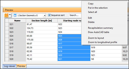
It is also possible to select Delete, and delete selected elements from the system (nodes or sections).
If you select column that shows pipe diameters, when you click Edit, the program will open command Input data for pipes, and you will be able to change pipe diameters for selected pipes.
· Draw AutoCAD table. Based on selection in the table, it is possible to draw AutoCAD table with selected elements and data values. When you start the command, select some table style (AutoCAD table configurations), and position it somewhere in the drawing area.
· Zoom to layout. If the option for automatic zoom has been turned off, another option enables zooming to specific section(s) or node(s). Based on selection (one or more entities) with right mouse button there is command Zoom to layout.
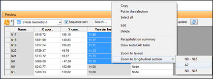
· Zoom to longitudinal section. It is possible to find selected element(s) (node or section) in longitudinal sections. Of course, longitudinal sections have to be drawn to use this option. If longitudinal sections were not drawn or selected element could not be found, the option will be disabled. If the element (section or node) exists in several longitudinal sections, all off them will be listed as shown on the picture below:
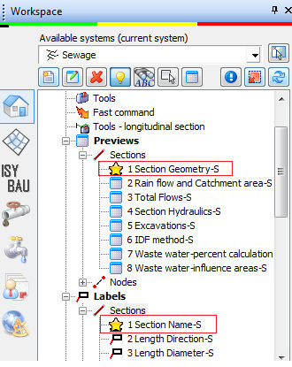
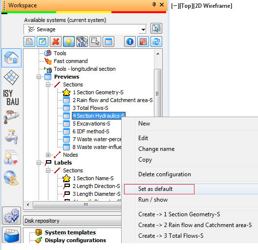
When using commands from Urbano ribbon or from the command line, the program will use default configuration. For example, when labeling elements or opening data tables. Default configuration is marked with star. Of course, it is easy to change default configuration.
WS System is the main part of the Workspace. It is empty when you open new, blank drawing.
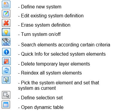
In this part of Workspace it is possible to create and edit new system, switch the system, turn the system on or off,
delete the system, check system information.
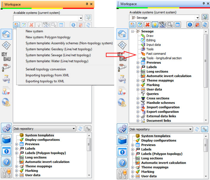
At the moment when you create new system, all system-related commands will appear.
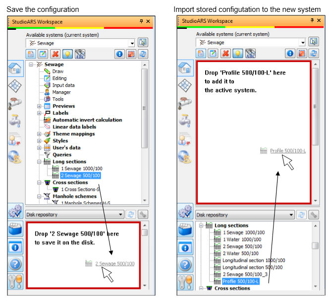
In WS - Disk repository you can store the configurations of labels, previews, longitudinal sections, and all other functions where you can create your own configuration. You can store the configuration in Disk repository using drag&drop – select the configuration, press the left mouse button and drag the configuration in Disk repository. After that, release left mouse button, and the configuration will be stored. It will be available in the Disk repository all the time, so you can use it in other drawings. You can take it to the new drawing using the same drag&drop method.
Important: First you have to open the new system.
 Repository configuration
– press this button to see available
functions on the tree view of the Workspace. By default, all available
functions will be marked, and will appear in the Workspace when you create
new system. If you unmark some of the functions, they won't be available
on the Workspace anymore, or in the part of the Disk repository. If you
turn it on again, you will be able to continue your work using those functions.
